Welding Flanges to Pipes: Weld Preparation and NDT Inspection Guide
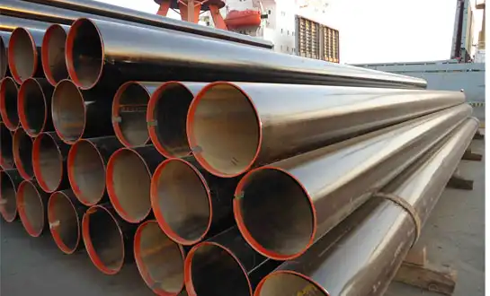
Welding flange to pipe connections represents a critical juncture in industrial piping systems, demanding precision in both execution and verification. This process involves permanently joining a flange—typically a welding neck, slip-on, or socket weld type—to a pipe section through fusion welding. Proper weld preparation and subsequent non-destructive testing (NDT) inspection are non-negotiable steps that determine the integrity, safety, and longevity of the entire piping system, particularly in high-pressure and hazardous environments.
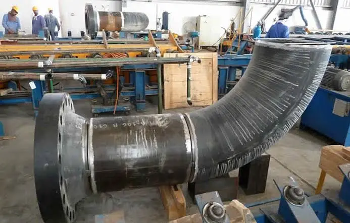
Understanding Welding Flanges to Pipes: Types and Applications
Primary Flange Types for Permanent Welded Joints
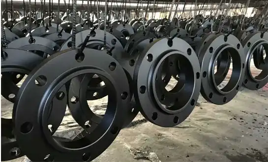
Different types of flanges are used in industrial piping systems, and each one is designed to meet specific operational needs. If you need to work with high pressure, the weld-neck flange is the best option. Its long, tapered hub provides structural reinforcement and smoothly transfers stress across the joint. These flanges are made from carbon steel (ASTM A105), alloy steel, and stainless steel types that all meet ASME B16.5 and EN 1092-1 standards.
Slip-on flanges are a cheaper option when pressure levels allow them. The pipe slips into the flange bore and requires dual fillet welds (at the outer hub and inside the bore). For compact layouts, socket weld flanges are ideal for small-bore piping of NPS 2 and smaller. When the pipe goes into a socket that is set back, it makes a smooth internal bore shape that keeps fluid flow systems from getting turbulent.
Lap joint flanges can be used with stub ends, which makes it easy to line them up during assembly. This configuration is useful when parts need to be taken apart often or when metals that are not the same need to be joined. These configurations are frequently specified in major energy projects approved by ADNOC and PETROBRAS for offshore platforms and refineries.
Material Selection and Standard Compliance
The material specification has a direct effect on how the weld is prepared and how it needs to be inspected. Carbon steel flanges are used in most low-pressure and water distribution systems because they are easy to make and cost-effective. Our carbon steel products are surface-treated by sandblasting and can be protected with anti-rust oil or water-based paint, helping extend service life in corrosion-prone environments.
Grades of stainless steel, especially 304L and 316L, are used in chemical processing and coastal environments where resistance to rust is very important. Alloy steel flanges with chromium, molybdenum, or nickel are used in power plants and industrial plants for high-temperature work. To maintain the required mechanical properties and prevent cracking, each type of material needs a different set of preheat temperatures and post-weld heat treatment methods.
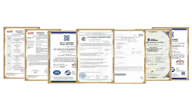
Following the rules set by ASME B16.5, EN 1092-1, and applicable GOST standards ensures that dimensions are correct and that materials can be traced back to their source. Our quality management system is certified to ISO 9001, and applicable products can be supplied with CE/PED 2014/68/EU documentation, along with full material test reports (MTR) and detailed paperwork. This certification system helps with buying choices by giving quality assurance that can be checked.
Weld Preparation for Welding Flanges to Pipes: Step-by-Step Guide
Surface Conditioning and Bevel Geometry
Carefully preparing the surface is the first step to successful welding. We use mechanical grinding or sanding to get rid of mill scale, rust, oil, and other contaminants. This leaves clean base metal within 25 millimetres of the weld area, reducing the risk of contamination-related defects such as porosity, slag inclusions, and hydrogen cracking. They weaken the joint's stability and require expensive repairs.
The geometry of the bevel must match the welding procedure specification (WPS). A typical V-groove shape may have a 30-degree bevel angle on each side, which adds up to a 60-degree included angle. Root faces and root openings are normally specified by the applicable WPS based on material thickness and welding process. These parameters make sure that the root pass welding goes deep enough without burning through.
Alignment and Fit-Up Precision
When you align things correctly, you avoid high-low misalignment, which causes stress to build up and flow to slow down. To keep the concentricity within the limits set by ASME B31.3, we use external clamps, internal line-up tools, and tack welds when welding flange to pipe. If the misalignment in the wall thickness exceeds the tolerance specified by the applicable code or WPS, engineers usually need to review it before moving forward.
Controlling the temperature is very important for the quality of the weld. Carbon steel components may require preheating depending on their carbon equivalent, thickness, material grade, restraint conditions, and applicable WPS. Preheating helps remove moisture and control the cooling rate to reduce the risk of hardening and cracking. To control grain growth and preserve toughness, the interpass temperature must remain within the limits specified by the applicable WPS. At regular times during the welding process, we use calibrated contact pyrometers or temperature-indicating crayons to check the temperatures.
Welding Process Selection and Execution
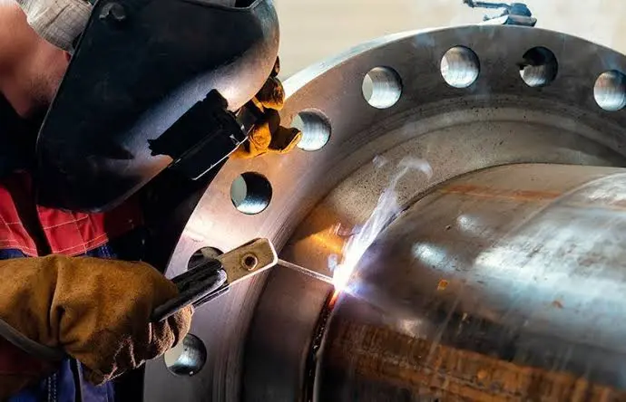
TIG (GTAW) welding is the preferred process for root passes on alloy and stainless steel piping because it produces high-purity weld beads with minimal spatter. Meanwhile, MIG (GMAW) or SMAW provides higher deposition rates for fill and cap passes on heavier carbon steel sections. Stick welding, or SMAW, remains common in field construction where portability is important. For each process, you need qualified welders whose qualifications meet the requirements of ASME Section IX or the applicable welding qualification standard in your country.
Traceability and regulatory compliance depend on good documentation practices. Weld maps give each joint a unique number that can be linked to information about the welder, the procedure, and inspection records. This paperwork is very important for audits and investigations into incidents involving pressure vessels because it shows that quality assurance is being done properly.
Non-Destructive Testing (NDT) Inspection for Welding Flanges to Pipes
Core NDT Methodologies and Selection Criteria
Visual testing (VT) is the first level of checking. It finds surface flaws like undercuts, crater cracks, and partial fusion before they get worse and cause service failures. When certified inspectors look at the weld profiles, reinforcement height, and surface finish, they compare them to the acceptance criteria in ASME B31.3 or the project specifications.
Radiographic testing (RT) uses X-rays or gamma radiation to make images that reveal internal discontinuities. This method is very good at finding porosity, slag inclusions, and areas of incomplete penetration. RT may be required for certain high-pressure or hazardous-service welds depending on the applicable code, fluid service category, and project specifications. The resulting X-rays are lasting records that help with following the rules and avoiding responsibility.
Ultrasonic testing, or UT, uses very high-frequency sound waves to find flaws deep inside things. Modern phased array UT systems can produce detailed cross-sectional images and detect relevant indications with sensitivity determined by the equipment, material, thickness, calibration, and applicable procedure. We use UT for important welds in places like power plants, chemical processing plants, and offshore sites where failure would be very bad.
Defect Interpretation and Remediation Protocols
Magnetic particle testing (MPT) and dye penetrant testing (DPT) are surface examination methods that reveal surface-breaking irregularities. MPT works with ferromagnetic materials like carbon steel, while DPT works with stainless steel and aluminium metals that are not magnetic. Both methods find fatigue cracks, grinding cracks, and heat-affected zone defects that cannot be detected by visual inspection alone.
Common weld defects appear in different ways during NDT. Porosity shows up as round marks that are caused by trapped gas during solidification. Slag particles have long forms because they weren't completely removed between weld passes. Lack of fusion shows up as straight lines along the fusion line. This is usually because there isn't enough heat or the technique is wrong. Cracks are the worst kind of flaw and need to be fixed right away, no matter how big or small they are, because they spread when the load is cycled.
Repair methods must follow strict rules. We grind or gouge away at the faulty weld metal, extending beyond the edges of the defect until clean base metal is seen. The repair cavity is inspected for dimensions and rewelded according to approved repair processes. It is then fully inspected again using the original NDT methods. This strict method makes sure that repaired welds meet the same standards for acceptance as the original work.
Comparing Welding Flanges in Procurement: Materials, Costs, and Suppliers
Material Performance in Demanding Environments
Corrosion resistance is what determines which materials are used in chemical processing and marine settings. Because it has molybdenum in it, stainless steel 316L is better than standard 304 grades at resisting chloride-induced pitting. Alloy steels with increased chromium content can provide improved oxidation and scaling resistance at elevated temperatures, but their performance depends on the specific alloy composition and service conditions, which is important for steam systems and thermal oil circuits.
Yield strength, tensile strength, and impact toughness are all parts of mechanical performance. Carbon steel flanges can be suitable for a wide range of working pressures and temperatures when the applicable material group and pressure-temperature rating are properly selected. Forged alloy steel with a suitable yield strength can be selected for high-pressure systems where the flange must withstand bolt loads without permanent deformation. Proper welding flange to pipe procedures then provide the required connection between the flange and pipe. Impact testing at the lowest temperatures allowed by design makes sure that the materials stay flexible, which keeps them from breaking easily when they start up in cold weather.
Lifecycle Economics and Bulk Procurement
Initial buying prices are only a small part of the total cost of ownership. Welding neck flanges are more expensive because they are harder to manufacture and use more material, but they can provide decades of reliable service when properly selected, installed, inspected, and maintained. Slip-on flanges are generally less expensive, but their suitability and inspection requirements depend on the design, service conditions, applicable codes, and project specifications, which adds up to more costs over the life of a project.
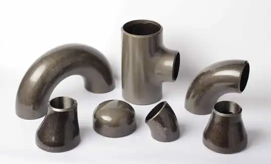
Bulk procurement can reduce purchasing and logistics costs while consolidating supplier relationships. By sourcing specialized sizes, such as reducing tees and large-diameter 90° elbows, from a single supplier, buyers can simplify vendor management. Our production capacity can handle project numbers ranging from small runs of prototypes to large contracts for many thousands of pieces. We keep quality constant through statistical process controls and automated dimensional checking.
Supplier Evaluation and Quality Assurance
When suppliers are bidding against each other, their certification portfolios help them stand out. Our ISO 9001:2015 quality management system makes sure that our manufacturing processes are always the same, and our GOST-R certification shows that we meet the standards of the Russian Federation. Vendor qualifications from leading international operators such as ADNOC (Abu Dhabi National Oil Company) and PETROBRAS demonstrate our proven capability in demanding energy markets.
Custom manufacturing lets you meet the special needs of a project that aren't met by standard catalogue items. We make hybrid flange designs that combine features from different standard configurations. We also machine custom bore diameters to fit non-standard pipe schedules and use specialised coatings like epoxy linings for potable water systems. This responsiveness in engineering speeds up project timelines by cutting down on the time it takes to find specialised components.
Installation Process and Dimensional Guidelines for Welding Flanges to Pipes
Pre-Installation Verification and Assembly Sequence
Before installation work starts, the dimensions are checked. We compare the outside diameter of the pipe with the flange bore to confirm adequate clearance for welding and shrinkage. We also verify the dimensions and condition of the raised face (RF). For Class 150 flanges, the face height is usually 1.5 millimetres, and for Class 2500 ratings, it rises to 6.4 millimetres. Serrated surfaces with a roughness of 3.2 to 6.3 micrometres improve the sealing performance of gaskets.
During construction, the bolt circle sizes and hole counts must be exactly the same. The bolt holes are set up so that when they are torqued, the load is spread out evenly. Stud bolts go through both sides and are held in place with heavy hex nuts on both ends. We use anti-seize compounds on threads to keep stainless steel parts from galling and to get correct torque-tension relationships.
Gasket Selection and Bolting Protocols
Materials used for gaskets should match the method and the type of face on the flange. Gaskets that are spiral wound and filled with graphite work well with high-temperature steam, while gaskets that are wrapped in PTFE can handle harsh chemicals. Ring-type joint (RTJ) gaskets fit into machined grooves on the faces of RTJ flanges to create metal-to-metal seals for high-pressure and high-temperature applications.
Tightening bolts is done in cross-pattern steps, moving forward in several passes until the design torque values are reached. First passes get 30% of the target force, then 60%, and finally 100%. This gradual tightening forces seals to be compressed evenly, which stops them from warping or leaking. When tightening large-diameter bolts, conventional torque wrenches may have accuracy limitations. Hydraulic torque wrenches can provide more controlled and repeatable tightening when specified for the application.
Pressure Class Ratings and Dimensional Standards
Pressure class numbers—150, 300, 600, 900, 1500, and 2500—identify pressure-temperature rating classes, with the allowable pressure depending on the flange material group and temperature. In carbon steel work, Class 150 flanges can handle 285 PSI at 100°F, and Class 2500 ratings can handle 6,170 PSI in the same settings. It is necessary to look at the pressure-temperature tables in ASME B16.5 because derating happens at high temperatures when the strength of the material drops.
The thickness of the flange goes up with the pressure class, which makes sure that the bolt can handle the load without giving way. A Class 150 welding neck flange with a nominal size of 6 inches is about 25.4 millimetres thick, while a Class 900 flange with the same nominal size is about 55.6 millimetres thick. These links between dimensions have a direct effect on the costs of materials and the amount of heat needed for welding, which in turn affects project budgets and plans.
Conclusion
Welding flange to pipe joints requires knowledge of material science, welding metallurgy, and process monitoring. Proper weld preparation and strict NDT help ensure faultless parts before pressure testing. Project success relies on procurement choices that balance initial costs and long-term performance. Following ASME, EN, and GOST guidelines throughout design, fabrication, and installation can help keep industrial pipe systems safe and functional for years.
FAQ
1. What is the difference between welding neck and slip-on flanges for pipe connections?
Welding neck flanges have a long, curved hub that makes the joint between the flange and the pipe stronger by spreading the stress over a bigger area. This style is better than slip-on styles at handling higher pressures and repetitive loading. Slip-on flanges fit over the end of the pipe and need fillet welds on the inside and outside. They are easier to install and cost less, but they work best in low-pressure situations. Weld neck flanges provide a butt-weld configuration that is suitable for volumetric examination such as RT or UT when required by the applicable code or project specification.
2. How often should NDT inspections be performed on high-pressure flange welds?
Initial inspection is performed after welding and any required post-weld heat treatment. Depending on ASME B31.3 requirements, project specifications, and fluid service category, selected welds may require radiographic or ultrasonic examination. The interval between in-service inspections depends on the variables of the process and the rules that apply. Critical systems may be subject to periodic visual and volumetric examinations at intervals established by the applicable inspection code, plant procedures, and risk-based inspection program. Facilities can set up risk-based inspection programmes that increase the number of inspections for corrosive services and decrease the number of inspections for harmless fluids.
3. Can custom flange sizes be fabricated for non-standard pipe schedules?
Custom manufacturing meets size needs that aren't covered by the normal ASME B16.5 guidelines. For any pipe schedule from Sch 10 to XXH wall thicknesses, we can make unique bore sizes that fit. Custom flange OD, bolt rings, and thickness can be made to fit different pressure levels or limited areas. For flanges larger than NPS 24, dimensions may be based on ASME B16.47 Series A or B when applicable, but they can be changed to fit your needs. Custom flange lead times are typically longer than those for stocked items, so early procurement planning is recommended.
Partner with RAYOUNG for certified welding flange solutions.
RAYOUNG makes flanges and pipe fittings with great care so they can meet the exact needs of EPC contractors, industrial end users, and infrastructure developers all over the United States. As a premier manufacturer and supplier of industrial pipe flanges, we produce components in carbon steel, alloy steel, and stainless steel. Our flange products can be supplied to applicable ASME B16.5, ASME B16.47, EN 1092-1, and GOST requirements. We deliver the certified quality your critical projects demand, with approvals from leading global energy corporations including ADNOC and PETROBRAS. Email our engineering team at info@hb-steel.com to talk about unique fabrication choices, get certifications for materials, or get quotes from other companies.
References
1. American Society of Mechanical Engineers. (2020). ASME B16.5: Pipe Flanges and Flanged Fittings NPS 1/2 Through NPS 24 Metric/Inch Standard. New York: ASME Press.
2. American Society of Mechanical Engineers. (2018). ASME B31.3: Process Piping—Design, Materials, Fabrication, Examination, and Testing. New York: ASME Press.
3. Becht, C., & Roberts, W. (2019). Welding Metallurgy and Weldability of Stainless Steels. Hoboken: John Wiley & Sons.
4. European Committee for Standardisation. (2017). EN 1092-1: Flanges and Their Joints—Circular Flanges for Pipes, Valves, Fittings and Accessories. Brussels: CEN Publishing.
5. Mix, P. E. (2015). Introduction to Nondestructive Testing: A Training Guide (Third Edition). Hoboken: John Wiley & Sons.
6. Smith, R. W., & Moffatt, D. G. (2021). Pressure Vessel Design Manual (Fifth Edition). Oxford: Butterworth-Heinemann.

Need a quote? Want to see samples? Just say hello. We’re friendly. We’re fast. And we’re ready when you are.
Welcome to RAYOUNG – Strong Pipes, Stronger Promise