Slip On Flange vs Weld Neck — Pressure Rating Compared
When choosing between slip-on flange vs. weld neck configurations, understanding pressure ratings becomes your most critical decision point. Slip-on flanges offer simpler installation and lower upfront costs, making them suitable for moderate-pressure applications. Weld neck flanges, with their tapered hub design and superior stress distribution, deliver enhanced reliability in high-pressure and high-temperature environments. This comparison helps procurement professionals balance performance requirements against budget constraints while maintaining safety and compliance standards across industrial piping projects.
Introduction
Flanges are critical components in industrial piping systems, providing essential connections between pipes, valves, and equipment in facilities worldwide. Choosing the right type of flange has a direct effect on the safety of the system, its dependability, and its ability to meet industry standards. In time-critical scenarios, this selection is paramount to project success.
This guide carefully examines the differences between slip-on and weld neck flanges, looking at their pressure limits, design features, and useful buying tips. This analysis was made for B2B procurement professionals who want to find the best flanges while also keeping performance needs and costs in mind. If you're in charge of an EPC contract, a distributor's stock, or government building projects, knowing these differences will help you keep risks to a minimum and get the most out of your investments in pipe systems.
Understanding Slip-On and Weld Neck Flanges
The main difference between these types of flanges is how they are built and how they are connected. Both are very important parts of pipe systems, but they are designed in very different ways.
Slip-On Flange Design and Characteristics
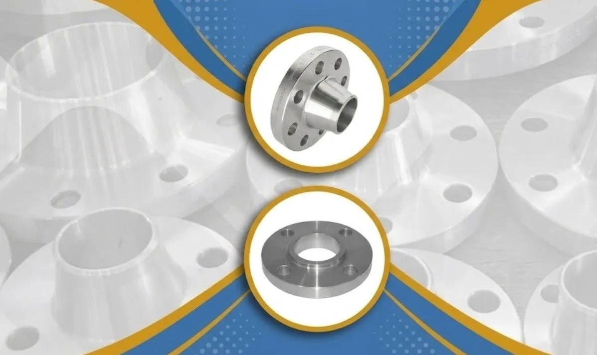
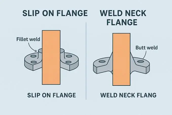
Slip-on flanges facilitate straightforward installation by allowing the pipe to be inserted directly into the flange bore prior to welding.The design lets you connect pipes directly and securely, and it can handle changes in temperature and pressure without the need for special adjustment tools. The inner diameter of the flange hole is a little bigger than the outer diameter of the pipe. This makes a space for both internal and external fillet welds. This design makes installation easier and cuts down on the time workers spend on job sites.
Most of the time, these flanges meet ASME B16.5 standards for pressure classes from Class 150 to Class 1500, depending on size and material requirements. There are different types of materials, such as carbon steel grades like ASTM A105 and stainless steel grades like ASTM A182 F304/F316, so they can be used in a range of situations. Standard gasket materials can be used with the flat-face form, which makes them easy for repair teams to get to.
Weld Neck Flange Construction and Advantages
Weld neck flanges have a long, curved hub that sticks out from the base of the flange. This makes the change in thickness from the flange face to the pipe wall more gentle. This tapering hub design is a big step forward in engineering because it moves the stress from the base of the joint to the pipe itself. The machined inner bore diameter matches the internal diameter of the connecting pipe. This makes a smooth flow path that removes turbulence and lowers the risk of erosion and rust.
A full-penetration butt weld is used to make the link, which allows for radiographic or ultrasonic examination when required by the applicable code or project specification, which is very important in critical or high-pressure systems. When compared to fillet welds, this way of welding makes the joint more stable. Materials for weld neck flanges are similar to those for slip-on designs, but they are often specified in more demanding grades when they need to have better mechanical qualities for important service conditions.
Weld neck flanges have a structure that makes them very resistant to fatigue even when they are loaded and unloaded many times. Thermal power plants, chemical processing plants, and offshore platforms often choose this type of flange for steam lines, high-pressure gas transfer, and subsea uses where servicing access is limited.
Slip-On Flange vs. Weld Neck Flange—Pressure Rating and Strength Comparison
The changes in pressure ratings between these flange types are caused by the way they are welded and how they are shaped. When procurement teams understand these distinctions, they can make informed decisions that safeguard both personnel and physical assets.
Maximum Allowable Working Pressure Analysis
When it comes to pressure rating in slip-on flange vs. weld neck comparisons, weld neck flanges always do better than slip-on designs. The curved hub better distributes stress across the flange-pipe joint, which allows these flanges to handle higher-pressure services when selected according to the applicable pressure-temperature ratings. The butt-weld connection makes a continuous path for the material that keeps the same stress levels even when the pressure changes.
Slip-on flanges are rated for the same pressure classes according to ANSI/ASME standards, but because they are filled in, they are not as strong in real life. The inside and outside double fillet welds make load accumulation points at the weld toes. These stress concentrations can develop fatigue cracks over time when subjected to prolonged high pressure or cyclic loading, especially if temperature changes make the mechanical stresses worse.
Fatigue Resistance and Cyclic Loading Performance
Most industrial processes don't work at steady pressure. When steam lines start up and stop, they go through thermal cycles. When the flow rate changes in a pipeline system, the pressure goes up. In these cyclical situations, the stability of the flange joint is always being tested.
Weld neck flanges have a tapered hub geometry that makes them very resistant to bending moments. This is because the hub length spreads stresses out evenly. When compared to slip-on designs, this one has a much longer fatigue life. According to research from pressure vessel standards, weld neck flanges generally provide better fatigue resistance than slip-on designs because their tapered hub reduces stress concentration.
Sealing Integrity and Leak Prevention
The risk of a leak goes up as pressure and warmth rise. Together, the raised face on weld neck flanges and their rigid hub design keep the gasket compressed evenly across the sealing surface. This steadiness is very important for keeping fugitive emissions from happening in chemical processes and hydrocarbon service.
Because of their fillet weld configuration, slip-on flanges experience higher stress concentration compared with weld neck designs when subjected to pressure and cyclic loading. In normal situations, gasket materials and the right amount of bolt torque can make up for this movement. However, for critical applications demanding zero-leak performance, weld neck configurations are typically required.
Application Scenarios and Cost Analysis
Choosing a practical application means weighing the costs and benefits of the project against the technical needs. Each type of joint has its own benefits in certain operating situations.
Optimal Use Cases for Slip-On Flanges
In situations with mild pressure and temperature, slip-on fittings work very well. Low-pressure steam lines, water distribution systems, and general utility piping all benefit from how cheap they are and how easy they are to install. The shorter welding time means that the project can be finished faster, which is especially helpful when replacing old flanges while the machine is shut down for repair.
Slip-on flanges offer acceptable performance while limiting capital expenditures in industries like commercial building systems, food processing plants, and municipal water treatment plants. Their design allows for quick changes in the field, which supports the flexible installation schedules that are common in smaller engineering projects.
Critical Applications Requiring Weld Neck Flanges
Weld neck flanges are commonly selected for high-pressure oil and gas applications where improved fatigue resistance and stress distribution are required. Internal pressures often go above 1,500 PSI, and systems are subject to large mechanical loads from ground movement and temperature changes. The integrity of the butt weld stops catastrophic failures that could put people and towns nearby in danger.
Weld neck flanges are extensively utilized throughout superheated steam systems in thermal power generation.It is possible for these lines to work at temperatures up to 1,000°F and pressures close to 3,500 PSI. The curved hub allows for expansion and contraction during temperature changes without affecting the quality of the seal. Offshore platforms and subsea systems only use weld neck designs because they are nearly hard to reach for repair. This means that long-term performance stability can't be compromised.
Total Cost of Ownership Considerations
Slip-on flanges initially cost 20–30% less than comparable weld neck models. But when you figure out the total cost of ownership in a slip-on flange vs. weld neck comparison, you have to include the labor costs of installation, the costs of inspections, and the possible outcomes of a failure.
Weld neck flanges need more skilled welders and more non-destructive testing, which raises the cost of fitting up front. But in critical service, these costs are nothing compared to the damage that could be caused by leaks, unplanned shutdowns, or safety violations. With weld neck installations, maintenance intervals tend to be longer, which lowers lifecycle costs by lowering the number of inspections and replacements that need to be done.
When planning, procurement managers should look at how available suppliers are, how much they need to be ordered, and how long it takes to get the goods. Standard sizes ship quickly from well-known makers, but special versions may take 8 to 12 weeks to make. Volume pricing often gives discounts of 15–25% on orders of more than 50 pieces, which makes strategies for consolidated procurement financially appealing.
Installation Processes and Dimension Specifications
How the joint is installed has a big effect on its quality and how well it works in the long run. Understanding the differences in how things are done helps project teams set realistic deadlines and assign the right resources.
Slip-On Flange Installation Procedures
To start the installation, slide the flange over the end of the pipe until it fits against the pipe surface. The oversized bore allows for minor pipe irregularities, so alignment is still easy. Then, welders do an internal fillet weld where the pipe end meets the flange bore and an external fillet weld around the outside flange thickness.
Proper weld gap and steady heat flow are very important for the quality of the weld. Inspectors usually look at finished welds visually and sometimes use dye penetrant testing to see if the welds are properly sealed. The process doesn't need as much specialized gear; normal arc welding tools and electrodes that are easy to find can be used.
Weld Neck Flange Installation Requirements
More accuracy is needed for weld neck placement. The pipe end needs to be beveled to match the bevel angle on the hub of the flange, which is usually 37.5 degrees according to ASME standards. Alignment tools make sure that the pipe bore and the flange bore are exact matches. This makes the smooth inside surface that is necessary for good flow.
The butt-weld process follows the qualified welding method standards. For carbon steel materials, it usually needs to be heated up first, and the cooling rate needs to be controlled to keep the steel from cracking. A radiographic or ultrasonic inspection makes sure that there are no defects and that the weld achieves full penetration. This strict quality assurance method takes a lot of time, but it provides proof of joint integrity that is needed to follow the rules.
Dimensional Standards and Material Compatibility
For sizes from NPS 1/2 through NPS 24, both flange types are generally covered by ASME B16.5 dimensional requirements. For bigger sizes, follow the rules in ASME B16.47. Some important measurements are the outside diameter, the bolt circle diameter, the number and size of bolt holes, and the width of the flange. These standard dimensions make sure that parts from different manufacturers can be used together.
The conditions of work affect the choice of material. Different types of carbon steel can be used for a wide range of tasks. Stainless steel doesn't rust in chemical environments. Alloy steels are strong at high temperatures. For projects to be properly documented and in line with regulations, materials must still be properly certified. This includes mill test results that show the materials' chemical composition and mechanical properties.
Conclusion
Slip-on flange vs. weld neck configurations are chosen based on application-specific needs that strike a balance between pressure ratings, fitting difficulty, and overall cost. Slip-on flanges provide a cost-effective solution for moderate-pressure systems, deriving their value from installation simplicity. Weld neck flanges are stronger, provide improved fatigue resistance, and seal well, which are all important qualities for high-pressure applications. The people who work in procurement have to weigh these scientific differences against the needs of the project, government rules, and long-term operating goals. Partnering with qualified makers who offer full technical support and high-quality paperwork is the best way to make sure that industrial piping projects choose the right flanges and that the systems will work reliably.
FAQ
1. What factors determine flange pressure ratings?
Pressure values depend on the type of material, the temperature, the ANSI/ASME flange class name, and the shape of the design. Since material strength goes down at higher temperatures, allowed pressure values go down as temperatures rise. Consulting pressure-temperature rating tables ensures the appropriate selection for specific service conditions.
2. Can slip-on flanges work in high-pressure applications?
Slip-on flanges can work in high-pressure class ratings as long as they are placed and kept correctly. But because they are made with a fillet weld, they are not as good as weld neck designs for critical high-pressure service where fatigue resistance and leak prevention are still very important. For temperatures over 1,000 PSI, most engineering standards say that weld neck flanges should be used.
3. How do delivery timelines differ between suppliers?
Standard flange sizes usually ship within two to three weeks from when they are in stock. Custom configurations take 8 to 12 weeks to make, based on how much material is available and how much the factory can make. International shipping takes an extra three to four weeks by ocean freight. Confirming lead times during the quotation process prevents disruptions to the project schedule.
Partner with RAYOUNG for Your Flange Procurement Needs
Picking the right flange supplier can affect how long a project takes, how well it turns out, and how reliable the system will be in the long run. RAYOUNG offers slip-on flange vs. weld neck options from certified production sites and blends industrial experience with customer-focused service. In household, business, and industrial settings, our range of carbon steel pipe fittings always works well. We keep our volume price affordable while also being able to meet your needs for custom specs and fast delivery. Our expert team is ready to talk with you about your unique application needs and make suggestions that balance performance standards with your budget. Email us at info@hb-steel.com to talk about your project needs, get technical specs, or get prices on standard and unique flange setups.
References
1. American Society of Mechanical Engineers. (2020). ASME B16.5: Pipe Flanges and Flanged Fittings. New York: ASME International.
2. Steel Founders' Society of America. (2019). Steel Castings Handbook: Supplement 9 - High Alloy Data Sheets. Des Plaines: SFSA.
3. Bickford, J.H. (2018). Gaskets and Gasketed Joints (2nd ed.). Boca Raton: CRC Press.
4. Maan, S. & Singh, R. (2017). Comparative Analysis of Flange Joints Under Cyclic Loading Conditions. Journal of Pressure Vessel Technology, 139(4), 041201.
5. International Organization for Standardization. (2021). ISO 7005-1: Metallic Flanges - Part 1: Steel Flanges. Geneva: ISO.
6. Campbell, R.D. (2016). Piping Systems Manual: Design, Construction, Maintenance. New York: McGraw-Hill Education.

Need a quote? Want to see samples? Just say hello. We’re friendly. We’re fast. And we’re ready when you are.
Welcome to RAYOUNG – Strong Pipes, Stronger Promise