Installing weld neck flange components in industrial pipe systems requires precision, expertise, and adherence to safety protocols. These critical pipe connections transfer stress effectively to the piping system while reducing high-stress concentration at the flange base, making them indispensable for high-pressure applications in oil, gas, petrochemical, and power generation facilities. Proper installation ensures long-term reliability, prevents costly downtime, and maintains system integrity across demanding industrial environments.

Understanding Weld Neck Flange Design and Benefits
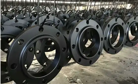
Weld neck flanges feature a distinctive tapered neck that provides exceptional strength and stress distribution capabilities. The gradual transition from the pipe wall to the flange face creates a smooth stress flow path, eliminating sharp corners that could become failure points under pressure. The welding neck design offers superior fatigue resistance compared to slip-on alternatives. This enhanced durability stems from the full-penetration butt weld between the pipe and flange, creating a structurally continuous connection that withstands thermal cycling and pressure fluctuations common in industrial applications. Material selection plays a crucial role in performance optimization. Carbon steel, stainless steel, and alloy steel variants accommodate different service conditions, temperatures, and corrosive environments. Each material grade provides specific advantages for particular industrial applications, ensuring compatibility with process requirements and environmental conditions. Dimensional accuracy and pressure rating compliance remain paramount considerations during specification. Standard dimensions conform to ASME B16.5 and ASME B16.47 (for large-diameter flanges), as well as international standards, guaranteeing interchangeability and system compatibility across global projects.
Pre-Installation Planning and Safety Requirements
Comprehensive planning prevents installation delays and ensures worker safety throughout the project lifecycle. Site assessment begins with evaluating existing piping conditions, accessibility constraints, and available workspace for welding operations. Documentation review encompasses flange specifications, material certifications, and welding procedure specifications. Verification of pressure ratings, temperature limits, and dimensional compliance prevents costly mistakes during installation phases. Safety protocols include establishing hot work permits, implementing fire prevention measures, and ensuring adequate ventilation for welding operations. Personal protective equipment requirements cover respiratory protection, eye shields, protective clothing, and fall protection systems where applicable. Tool and equipment preparation involves calibrating welding machines, preparing cutting tools, and organizing measurement instruments. Quality control equipment, such as dye penetrant testing materials and radiographic testing capabilities, should be readily available for post-weld inspections.
Step-by-Step Installation Procedures
Pipe preparation begins with accurate measurement and cutting operations. The pipe end requires perpendicular cuts with smooth, clean surfaces free from burrs, scale, or contamination that could compromise weld quality. Flange positioning involves aligning the welding neck with the pipe end, ensuring proper gap dimensions and concentricity. Tack welding at multiple points maintains alignment during the welding process while allowing for thermal expansion. Root pass welding establishes the foundation for subsequent weld layers. Penetration depth, bead profile, and heat input control prevent defects such as lack of fusion, porosity, or excessive distortion that could affect system performance. Fill passes and cap passes complete the joint while maintaining specified weld profiles. Each pass requires interpass temperature control, cleaning between layers, and visual inspection to identify potential defects before proceeding. Post-weld heat treatment may be required depending on material specifications and service conditions. Stress relief operations reduce residual stresses that could contribute to premature failure in high-temperature applications.
Quality Control and Testing Protocols
Visual inspection represents the primary quality control method during and after welding operations. Trained inspectors examine weld profiles, surface conditions, and dimensional compliance according to applicable codes and standards. Non-destructive testing methods verify internal weld quality without compromising joint integrity. Radiographic testing reveals internal discontinuities, while ultrasonic testing provides alternative inspection capabilities where radiography proves impractical. Dye penetrant testing identifies surface-breaking defects that might escape visual detection. This cost-effective method suits field applications where sophisticated testing equipment availability remains limited. Pressure testing validates installation integrity under controlled conditions before system commissioning. Hydrostatic or pneumatic testing procedures follow established protocols that simulate operating conditions while maintaining safety margins. Documentation requirements include maintaining detailed records of materials used, welding parameters, weld neck flange inspection results, and test outcomes. These records support warranty claims, regulatory compliance, and future maintenance planning.
Common Installation Challenges and Solutions
Alignment difficulties frequently occur when connecting to existing piping systems with dimensional variations. Field measurements and custom machining may be necessary to accommodate these variations while maintaining code compliance. Welding position constraints in congested plant areas require specialized techniques and qualified welders experienced in overhead and vertical welding positions. Access platforms and specialized equipment facilitate quality welding in challenging locations. Material compatibility issues arise when connecting different steel grades or specifications. Welding procedure qualifications must address these combinations, ensuring adequate mechanical properties and corrosion resistance. Weather conditions affect field welding operations, particularly in outdoor installations. Wind shields, preheating equipment, and environmental protection measures maintain weld quality regardless of ambient conditions. Schedule pressures sometimes compromise quality unless proper planning allocates sufficient time for each installation phase. Rushed installations increase defect rates and rework requirements that ultimately delay project completion.
Maintenance and Long-term Performance Optimization
Regular inspection schedules identify potential issues before they escalate into costly failures. Visual examinations, gasket condition assessments, and bolt torque verification maintain joint integrity throughout the service life. Corrosion monitoring becomes critical in aggressive environments where chemical exposure or atmospheric conditions threaten flange longevity. Protective coatings, cathodic protection, or material upgrades may be necessary for extended service life. Thermal cycling effects require periodic assessment of joint tightness and gasket condition. Expansion and contraction stresses can loosen bolted connections or damage sealing surfaces over time. Replacement planning considers factors such as remaining service life, maintenance costs, and system upgrade opportunities. Proactive replacement prevents unexpected failures that could disrupt critical operations. Performance data collection supports continuous improvement initiatives and future design optimization. Operating experience feedback enhances specification development for similar applications and environments.

Conclusion
Successful weld neck flange installation requires careful planning, skilled execution, and rigorous quality control throughout the process. These critical connections provide superior strength and reliability in demanding industrial applications where system integrity cannot be compromised. Proper installation techniques, combined with appropriate material selection and thorough testing, ensure long-term performance that meets operational requirements. Investment in quality components and professional installation practices delivers significant returns through reduced maintenance costs, extended service life, and minimized downtime risks. The expertise and attention to detail invested during installation directly impact overall system reliability and operational success.
Partner with RAYOUNG for Premium Weld Neck Flange Solutions
RAYOUNG delivers comprehensive weld neck flange solutions backed by ISO 9001:2015 certification and proven manufacturing excellence. Our extensive product range encompasses carbon steel, stainless steel, and alloy steel options that meet stringent industry standards, including ASME B16.5 and international specifications. With GOST-R (or equivalent regional conformity) and SGS certifications supporting export compliance, we serve as your trusted weld neck flange supplier for critical industrial applications. Experience reliable performance, competitive pricing, and technical support that minimizes project risk while meeting demanding deadlines. Contact us at info@hb-steel.com to discuss your specific requirements.
References
1. American Society of Mechanical Engineers. "ASME B16.5 - Pipe Flanges and Flanged Fittings: NPS 1/2 Through NPS 24 Metric/Inch Standard." ASME International, 2020.
2. American Petroleum Institute. "Recommended practices for installation of welded steel piping in industrial applications." API Standards Department, 2019.
3. International Organization for Standardization. "ISO 15156-3: Petroleum and Natural Gas Industries - Materials for Use in H2S-containing Environments in Oil and Gas Production." ISO Publications, 2020.
4. National Association of Corrosion Engineers. "NACE SP0472: Methods and Controls to Prevent In-Service Environmental Cracking of Carbon Steel Weldments in Corrosive Petroleum Refining Environments." NACE International, 2018.
5. American Welding Society. "AWS D1.1/D1.1M: Structural Welding Code - Steel." AWS Publications, 2020.
6. British Standards Institution. "BS EN 1092-1: Flanges and their Joints - Circular Flanges for Pipes, Valves, Fittings and Accessories." BSI Standards Limited, 2018.