Pipe and Flange Welding: Quality Control for Leak-Free Joints
Achieving leak-free pipe and flange welding requires a comprehensive understanding of quality control principles, proper material selection, and adherence to industry standards. In industrial piping systems, welded flange joints serve as critical connection points where failure can result in costly downtime, safety hazards, and environmental risks. Effective quality control measures—ranging from pre-weld preparation through final inspection—ensure these joints withstand high pressures, corrosive environments, and thermal cycling throughout their operational lifespan. This article explores proven strategies that procurement managers, engineers, and installers rely upon to minimise risk and maximise system integrity.
Understanding Pipe and Flange Welding Fundamentals
Gaining a strong understanding of flange welding principles helps you make smart choices during the purchasing and installing stages. The technical requirements, industry standards, and safety rules we talk about here have a direct effect on the success of the project and its dependability in the long run.
Defining Pipe Flanges and Their Critical Role
In industrial systems, pipe flanges are mechanical parts that make it easier to bolt together pipes, valves, pumps, and other equipment. These bolted connections distribute the clamping force across the joint, which lets the parts be taken apart for repair while maintaining pressure containment. Flanges allow system flexibility without compromising structural integrity in petrochemical plants, water treatment plants, and power plants. When the flange meets the right specifications, it stops leaks in a wide range of operating conditions, from very cold temperatures to high-pressure steam.
Key Flange Types for Welding Applications
Different flange designs meet different technical needs based on pressure levels, installation limitations, and the need to make sure that the materials used are compatible.
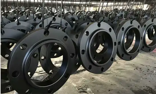
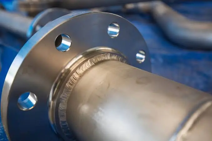
For critical applications, weld-neck pipe flanges are the most reliable choice. These flanges feature a long, tapered hub that transitions gradually from the heavy flange forging to the nominal wall thickness of the mating pipe. This provides a smooth, tapered transition from the flange bore to the pipe, which helps reduce local stress concentrations and turbulence. The design of the weld neck lets X-rays look at the butt weld, which makes sure that the weld goes all the way through and there are no flaws in the joints. According to ASME B16.5 standards, these flanges can withstand pressures from Class 150 to Class 2500. They are commonly made from forged ASTM A105 carbon steel and ASTM A182 F316 stainless steel. The bore diameter is matched to the inside diameter and wall thickness of the joining pipe, which allows for the best flow properties in systems that work with corrosive materials or at high temperatures.
Slip-on flanges are a cheap way to fix problems in low-pressure situations where fitting speed is important. The pipe is slid into the flange hole, and then it is fillet-welded inside and outside the hub. This design needs two separate welds and cannot be examined as readily by radiography as the butt weld of a weld neck configuration, but it is easier to line up during assembly.
Plate flanges are used in certain ways in low-pressure utility systems and water distribution systems. These flanges are made from flat plate stock that may meet ASTM A240 for stainless steel grades or ASTM A36 for carbon steel, with the applicable flange design and dimensional requirements specified separately. They do not have the same grain-flow characteristics associated with forged products but are very flexible and easy to customise. Thickness and outer diameter can be machined to meet the needs of a particular project, going beyond the standard ASME B16.5 measurements and often following AWWA C207 guidelines. Because there is no hub, double fillet welds are needed to make sure the connection is stable, and the surface is usually machined to a roughness of Ra 3.2–6.3 µm to get the best gasket sealing performance.
These different types of flanges meet different practical needs. This lets engineers combine mechanical performance with installation timelines and budgets.
Welding Process Overview and Industry Standards
Before the flange welding process can start, the pipe must be carefully prepared by bevelling, cleaning, and making sure it fits correctly. The ends of pipes made of ASTM A106 or API 5L carbon steel are bevelled to help the weld go through properly and make the joint stronger. For approved methods that tell them how much heat to use, the temperature between passes, and which filler metal to use based on the base material's chemistry and the conditions of service, welders follow them.
Every part of making a flange joint is governed by industry codes. ASME B31.3 talks about process piping in chemical plants and refineries, and ASME B16.5 talks about flange sizes and ratings for pressure and temperature. API 1104 talks about welding in pipelines, and ISO 15614 sets international standards for weld procedure qualification. Following these rules makes sure everyone is safe, makes it easier for insurance companies to approve claims, and meets legal requirements in many places. According to NACE MR0175/ISO 15156 rules, projects that will be used in sour service settings need materials and methods that can prevent sulphide stress cracking.
Safety Considerations in Flange Welding
Welding activities have many risks that need to be managed in a planned way. Arc flash protection, good airflow to keep people from breathing in toxic fumes, and fire safety rules all help keep people safe during manufacturing. Some material-specific issues to think about are the need to preheat carbon steel alloys to stop hydrogen cracking and the need for a post-weld heat treatment to relieve residual stresses in thick-section parts. When engineers design welded assemblies, they have to take thermal expansion into account. They have to make sure that the bolt loads stay the same over temperature cycles so that the gasket materials or flange faces don't get too stressed.
Ensuring Quality Control for Leak-Free Flange Joints
Strict quality control methods, including pipe and flange welding, separate systems that are likely to fail from those that are likely to work. Finding and fixing welding flaws has a direct effect on the safety of the system and its ability to keep running.
Common Welding Defects and Their Consequences
When gas areas get stuck in hardening weld metal, this is called porosity. This can happen because the base material is dirty, the electrodes are wet, or there isn't enough shielding gas coverage. These holes make it harder for the structure to hold weight and create leak paths when the pressure changes. Cracks are the worst kind of flaw. They can be caused by too much control, hydrogen embrittlement, or choosing the wrong filler metal. Longitudinal cracks that run parallel to the weld centreline and transverse cracks that run perpendicular to it both require the whole joint to be taken apart and welded back together again.
When there is an undercut, the base metal has melted away without enough filler being deposited, leaving groove-like depressions along the weld toe.This geometry creates localized stress concentrations that substantially accelerate fatigue failure under cyclic pressure loading. If there is incomplete fusion between weld passes or at the weld root, seepage paths can form, which greatly lowers the strength of the joint. When pipes that should fit together aren't lined up correctly, they create bending stresses and turbulence that damage more quickly through corrosion and erosion.
Advanced Inspection Techniques
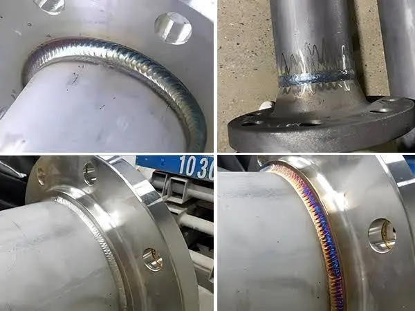
Visual inspection is the first step in making sure of the quality, finding things like surface flaws, spatter, and differences in size. To find problems in heat-affected zones, trained testers look at the bead shape, how the toes blend together, and any changes in colour. Radiographic testing with X-rays or gamma radiation shows cracks inside that can't be seen from the outside. Film interpretation finds porosity clusters, slag inclusions, and flaws that don't go through the material. The acceptance criteria are established by the applicable piping or equipment code, such as ASME B31.3, ASME B31.1, or the applicable project specifications.
Ultrasonic testing uses high-frequency sound waves to find flaws below the surface without worrying about radiation exposure. Phased array UT provides detailed cross-sectional images of weld zones, which helps inspectors evaluate complex geometries and discontinuities. Liquid penetrant testing is used to detect surface-breaking discontinuities on clean, nonporous materials, while magnetic particle inspection finds surface and near-surface discontinuities in ferromagnetic materials. Each technique is used to fix a different kind of defect, and complete programmes use more than one technique for key parts.
Comprehensive Flange Weld Inspection Checklist
For pre-weld verification, positive material identification using XRF or optical emission spectroscopy is used to verify key alloying elements and compare the material with the mill test report and project requirements. Dimensional inspection ensures that the flange bore (internal diameter) precisely matches the inside diameter of the adjoining pipe schedule. Differences between Sch 40 and Sch 80 affect the pipe wall thickness, weight, bore diameter, and allowable pressure calculations. Verification of surface preparation shows that mill scale, rust, and other contaminants have been removed within an inch of the joint.
During welding, monitoring includes looking at the welder's qualification records, making sure the process is followed when it comes to amperage and travel speed, and measuring the temperature between passes. Keeping track of filler metal heat numbers makes it possible to trace materials if problems are identified after they have been used.
Post-weld examination includes the nondestructive testing methods we've already talked about, as well as dimensional surveys that make sure the bolt holes are lined up and the flange face is parallel. Using the Brinell or Rockwell methods to test hardness verifies that heat-affected areas remain within the specified hardness limits. During hydrostatic testing, finished assemblies are tested at the pressure required by the applicable piping or equipment code and project specifications. This makes sure that there are no leaks before they are put into service.
These regular checks give concrete proof that parts meet engineering standards, which helps quality control programmes and legal compliance.
Design Principles for Optimised Joint Integrity
The right choice of seal materials for the service temperature, pressure, and chemical exposure goes hand in hand with good welding. Spiral-wound seals with graphite filler are commonly used in many hydrocarbon services, while PTFE-envelope types may be suitable for certain corrosive chemical services. Bolt torque patterns make sure that the tightening force is spread out evenly, which protects the gasket and keeps the seal compressed. Engineers use ASME PCC-1 guidelines to determine appropriate assembly bolt loads and tightening methods, taking into account things like internal pressure, thermal expansion, and the reduction of gasket stress over time.
Comparing Welding Techniques and Materials for Optimal Performance
Correct pipe and flange welding procedures and materials determine a part's performance under varied operating conditions. Knowing each method's pros and cons helps you choose safe, affordable solutions.
Welding Versus Bolting: A Strategic Analysis
Leak-free permanent welded connections are better for hazardous and high-pressure fluids than threaded or bolted joints. Properly designed welded connections can provide good fatigue performance under vibration, while bolted flanged joints offer the advantage of easier maintenance and disassembly. Valves and equipment may be removed without cutting lines. Flanged equipment tie-ins with bolted connections help projects balance these requirements. It keeps systems safe and easy to repair.
Welding Process Selection Based on Application Requirements
Shielded metal arc welding (SMAW) is still used for field installations since it needs minimal equipment and can withstand wind. Manual electrode welding on large-diameter pipe flanges is commonly used in chemical plants and manufacturing facilities. When thicker materials require multiple controlled heat passes, appropriate travel speeds and heat input must be maintained.
GTAW/TIG is suitable for root passes on metal and stainless steel flanges. The inert gas shield protects the molten metal from atmospheric contamination, helping create clean, sound welds for sour service applications. Lower deposition rates increase labour costs but reduce repair costs.
For fill and cap passes on moderate-thickness flanges, GMAW/MIG simplifies carbon steel installation. Semi-automatic wire feeds reduce welder fatigue and stabilise many connections in production. Flux-cored versions may be used outdoors without shielding gas.
SAW deposits weld metal on large shop-made weld neck flange assemblies for heavy-wall pipe faster. Granular flux blankets protect the arc and improve weld metal chemistry, making radiographically inspectable welds more efficiently. Automated process settings help maintain consistent bead geometry and penetration.
Matching process capabilities to material thickness, site accessibility, and quality standards boosts productivity without losing quality.
Material Compatibility and Filler Metal Selection
The most prevalent pipe part is carbon steel ASTM A105 forging flanges. Strong and ductile, they can be welded with E7018 electrodes or ER70S-6 wire when permitted by the qualified welding procedure. For corrosion-resistant ASTM A182 F316 stainless steel flanges, use compatible 316L filler metals selected according to the qualified welding procedure. Carbon steel pipe-stainless flange couplings may require nickel-based or other compatible filler metals, such as ERNiCrMo-3, depending on the base materials, welding procedure, and service conditions to account for temperature expansion and avoid brittleness.
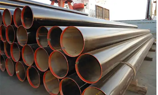
Carbon steel pipes ASTM A106 and API 5L are available in a range of schedules, including 10–160, where applicable. They use similar flange pressure classes to maintain system pressure. Their precision-machined beveled ends simplify joint fit-up, while factory-applied anti-corrosion coatings protect the exterior surface during transit and storage. Properly welded sour service pipes have controlled sulphur and phosphorus levels that avoid hydrogen cracking.
Matching materials reduces galvanic corrosion, preserves mechanical properties, and helps ensure that welds meet or exceed the required mechanical and service-performance criteria.
Conclusion
To get leak-free pipe and flange welding, you need to pay attention to choosing the right materials, following the right steps, inspecting carefully, and doing regular upkeep. The steps explained here, from learning the basics of flange construction to fixing problems in the field, help procurement managers and installation teams keep project risks to a minimum and costs under control. When you combine certified welding methods, thorough inspection routines, and high-quality parts that meet ASTM and API standards, you get joints that are reliable and can handle tough service conditions. Strategic partnerships with experienced suppliers give complex industrial projects the technical support and material traceability they need, making sure that every connection point stays solid for decades of use.
FAQ
1. What causes flange weld leaks and how can they be prevented?
Leaks usually happen when the fusion isn't complete, there are holes, or the gasket isn't compressed enough. To avoid problems, you need to use the right amount of heat during the welding process, clean the area well before the welding starts, and do full nondestructive testing to find any hidden flaws before the pressure is applied. When you use calibrated tools and the right bolt torque sequences, the gasket is loaded evenly across the flange face.
2. How do you select welding techniques based on flange materials?
Carbon steel flanges can be used with all common processes, such as SMAW, GMAW, and SAW, depending on the needs of the production process and accessibility. For stainless steel and alloys, TIG root passes are best for making sure the first layers are clean and free of holes. For fill passes, MIG or stick processes work better because they are faster. Within the limits of the qualified procedure, amperage ranges and travel speeds are set by the thickness and position of the material.
3. Can flange welds be repaired on-site, or does replacement become necessary?
Small flaws on the surface, like small undercuts, can usually be fixed by grinding and mixing within the limits allowed by the code, without the need for extra welding. Cracks and large holes need to be completely fixed by removing the flaw and then re-welding using approved repair methods. Depending on the material and thickness, this may require a post-weld heat treatment. If you try to fix severely damaged flanges more than once, you should probably just replace them to make sure they last a long time.
Partner with RAYOUNG for Reliable Pipe and Flange Welding Solutions
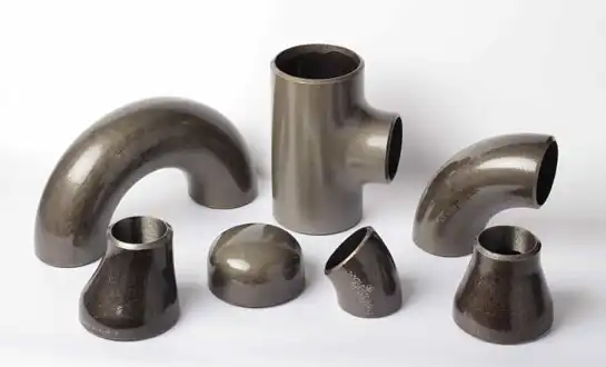
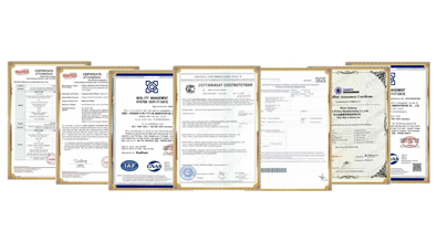
RAYOUNG is ready to help you with your next industrial piping job by providing you with a wide range of materials and professional advice. We have been a trusted manufacturer and supplier of weldable pipes, flanges, and piping systems for nearly two decades. We offer ASTM A106 and API 5L carbon steel pipes in schedules 10–160. These pipes come with approval for hydraulic testing, bevelled ends that are best for welding, and paperwork that shows they meet sour-service compliance standards. We have weld neck, slip-on, and plate flanges in stock that are made to ASME B16.5 standards. To complete system solutions, we also have butt-weld elbows, reducers, and custom fittings. We are committed to quality throughout production and delivery, as shown by our ISO 9001:2015 certification and GOST-R and SGS validations. Contact our knowledgeable staff at info@hb-steel.com to talk about your unique needs and find out how our product line and technical support can make your purchasing process easier while still ensuring leak-free performance.
References
1. American Society of Mechanical Engineers. (2020). ASME B16.5: Pipe Flanges and Flanged Fittings: NPS 1/2 through NPS 24 Metric/Inch Standard. New York: ASME Press.
2. American Petroleum Institute. (2019). API Standard 1104: Welding of Pipelines and Related Facilities, 21st Edition. Washington, DC: API Publishing Services.
3. Becht, C. (2018). Process Piping: The Complete Guide to ASME B31.3, Fourth Edition. New York: ASME Press.
4. International Organisation for Standardisation. (2017). ISO 15614-1: Specification and Qualification of Welding Procedures for Metallic Materials - Welding Procedure Test - Part 1: Arc and Gas Welding of Steels. Geneva: ISO Central Secretariat.
5. Lansinger, S. and McIntyre, D. (2016). Guidelines for Pressure Boundary Bolted Flange Joint Assembly: ASME PCC-1-2013. New York: ASME Standards Technology.
6. NACE International. (2015). NACE MR0175/ISO 15156: Petroleum and Natural Gas Industries – Materials for Use in H₂S-Containing Environments in Oil and Gas Production. Houston: NACE International Publications.

Need a quote? Want to see samples? Just say hello. We’re friendly. We’re fast. And we’re ready when you are.
Welcome to RAYOUNG – Strong Pipes, Stronger Promise