How to Calculate the Right Pipe Bend Radius for Your Project?
One of the most basic engineering tasks, determining the proper pipe bend radius has an effect on system performance, installation costs, and operating reliability in the long run. Pressure losses, structural strains, and the fluid flow characteristics are all impacted by the sharpness with which a pipe changes direction, which is defined by the bend radius. Overly turbulent flow, early wear, or installation issues could result from choosing the wrong radius. Space limits, hydraulic efficiency needs, material capabilities, and manufacturing limitations are just a few of the considerations that engineers must consider when defining bend geometry. When ordinary components fail to meet the project's precise dimensional specifications or performance standards, engineers can craft engineered solutions with custom pipe bends. If one is well-versed in the relevant calculation methodologies, industry standards, and practical concerns, they may make well-informed decisions that optimize investment and lifespan costs while also assuring safe and efficient operation in conformity with relevant regulations.

Fundamental Principles of Bend Radius Calculation
Understanding the Radius-to-Diameter Ratio
The radius-to-diameter ratio, commonly expressed as R/D, represents the relationship between the centerline bend radius and the nominal pipe diameter, serving as the primary parameter defining bend geometry. Industry standards typically classify bends into long radius configurations with R/D ratios of 1.5, short radius designs at 1.0 R/D, and custom specifications falling outside these standard categories. Long radius bends provide gentler directional changes that minimize pressure drop and reduce flow turbulence, making them preferable for applications prioritizing energy efficiency and pump performance. The smoother flow path through long radius bends reduces erosion potential in systems handling abrasive slurries or high-velocity fluids, extending service life and reducing maintenance requirements. Short radius bends occupy less physical space, offering advantages in congested piping arrangements where installation footprint constraints override hydraulic considerations. Custom pipe bends with non-standard R/D ratios address specific project needs where space limitations, equipment positioning, or three-dimensional routing requirements demand tailored solutions. Engineers must evaluate trade-offs between hydraulic performance, space utilization, and manufacturing feasibility when selecting the appropriate radius ratio. Calculating the actual centerline radius involves multiplying the nominal pipe diameter by the desired R/D ratio, yielding the radius measurement from the bend center point to the pipe centerline throughout the curved section.
Pressure Drop and Flow Velocity Considerations
Accurate bend radius calculation requires comprehensive analysis of pressure drop characteristics and their impact on system performance and operating costs. Fluid flowing through pipe bends experiences secondary flow patterns where centrifugal forces create spiral motion, increasing friction losses beyond those in straight pipe sections. The resistance coefficient for bends, often denoted as K-factor, quantifies additional pressure loss as a function of velocity head, with values varying based on bend radius, pipe diameter, and flow Reynolds number. Longer radius bends exhibit lower K-factors, translating to reduced energy consumption in pumped systems operating continuously over extended periods. Engineers must calculate total system pressure drop including all bends, fittings, and straight pipe sections to ensure adequate pump sizing and verify that available pressure meets process requirements at design flow rates. High-velocity applications require particular attention to bend radius selection because pressure losses increase proportionally to velocity squared, making radius optimization critical for energy efficiency. Custom pipe bends designed with optimized radii for specific flow conditions can deliver significant operational savings in large-diameter systems or high-flow applications where energy costs constitute major operational expenses.
Material Stress and Structural Integrity Analysis
Bend radius calculations must account for material stresses induced during both manufacturing and service to ensure structural integrity throughout the design life. During the bending process, the outer wall experiences tensile stress causing thinning on the extrados, while the inner wall undergoes compression resulting in thickening on the intrados. The degree of wall thickness variation correlates inversely with bend radius, meaning tighter bends produce more pronounced thickness changes that must be accommodated in initial pipe wall selection. Structural analysis evaluates hoop stress from internal pressure, longitudinal stress from end forces, and combined stress states at critical locations to verify compliance with allowable stress criteria defined by applicable design codes. Custom pipe bends manufactured for critical applications often incorporate finite element analysis verifying stress distributions under actual loading conditions including deadweight, pressure, thermal expansion, and external loads from supports or connected equipment. Minimum bend radius limitations for specific materials prevent excessive cold work that could reduce ductility or create residual stresses compromising service performance.
Standard Calculation Methods and Design Codes
ASME B16.9 and International Standards Application
The American Society of Mechanical Engineers B16.9 standard provides dimensional specifications and tolerances for factory-made wrought steel butt-welding fittings, including comprehensive requirements for pipe bends used throughout industrial applications. This standard defines centerline radius dimensions, wall thickness requirements, and geometric tolerances ensuring interchangeability and predictable performance across manufacturers. Engineers reference ASME B16.9 tables specifying minimum bend radii as functions of nominal pipe size, with standard long radius fittings maintaining 1.5D centerline radius and short radius fittings at 1.0D regardless of diameter. International standards including DIN, JIS, and GOST provide alternative specifications that may apply based on project location or specific industry practices. Custom pipe bends not conforming to standard dimensions require detailed engineering calculations verifying that proposed geometry meets strength requirements under design conditions.
Hydraulic Calculation Procedures
Hydraulic calculation procedures for bend radius selection integrate fluid mechanics principles with empirical data correlating geometry to pressure loss characteristics. The Darcy-Weisbach equation modified with bend loss coefficients quantifies pressure drop as functions of fluid density, velocity, and geometric parameters. Engineers typically employ equivalent length methods where bends are represented as equivalent straight pipe lengths producing identical pressure losses, simplifying system calculations. Reynolds number calculations determine flow regime characteristics influencing loss coefficient selection. Custom pipe bends serving specialized applications may require testing to establish actual pressure loss characteristics, particularly involving unusual fluids or extreme temperatures. System optimization algorithms can evaluate multiple bend radius alternatives, identifying configurations that minimize total installed cost while meeting hydraulic performance targets.
Code Compliance and Safety Factor Application
Design code compliance ensures that calculated bend radii meet minimum safety standards established through industry experience. Piping codes including ASME B31.1 for power piping, B31.3 for process piping, and B31.4 for liquid transportation specify allowable stress criteria, minimum wall thickness requirements, and flexibility analysis procedures. Safety factors embedded within code formulas account for uncertainties in material properties and loading conditions. Custom pipe bends in high-consequence applications may require enhanced safety margins beyond minimum code requirements. Third-party review provides independent verification that design calculations and material selections comply with regulatory requirements.
Practical Application and Project-Specific Considerations
Site Constraints and Installation Limitations
Real-world projects impose practical constraints that significantly influence bend radius selection beyond theoretical calculations. Physical space limitations in existing facilities, congested pipe racks, or building structural elements may preclude optimal radius configurations. Underground installations must account for minimum cover requirements, existing utility conflicts, and excavation limitations. Modular construction approaches must consider transportation envelope restrictions limiting overall spool dimensions. Custom pipe bends designed for retrofit projects must interface with existing piping maintaining precise alignment. Welding accessibility around bend regions influences joint design and may require special procedures. Pre-installation verification using three-dimensional laser scanning confirms that fabricated bends match design geometry before installation.
Material Properties and Manufacturing Feasibility
Material characteristics fundamentally affect achievable bend radii and appropriate calculation methods. Carbon steel materials offer excellent formability allowing relatively tight minimum bend radii. Stainless steel alloys exhibit different work hardening characteristics requiring larger minimum radii or intermediate annealing. High-strength materials may necessitate hot forming processes to achieve desired geometry. Pipe wall thickness relative to diameter influences minimum achievable radius. Custom pipe bends in exotic materials may require trial bending establishing feasible manufacturing parameters. Heat treatment requirements affect lead times and manufacturing costs. Quality assurance testing verifies that formed bends retain specified mechanical properties after forming operations.
Cost Optimization and Economic Analysis
Economic considerations significantly influence bend radius decisions, with cost optimization balancing initial procurement against lifecycle operating expenses. Standard radius bends typically cost less than custom configurations requiring special tooling. Larger radius bends consume more material and increase shipping costs despite hydraulic advantages. Energy cost analysis quantifies operational savings from reduced pressure drop in longer radius configurations. Custom pipe bends optimized for specific applications may deliver economic benefits through improved system performance offsetting higher initial prices. Total cost of ownership analysis incorporates procurement, installation labor, energy consumption, and maintenance requirements, providing comprehensive economic comparison between alternative strategies.
Conclusion
Calculating the right custom pipe bends for sale radius requires comprehensive analysis integrating hydraulic performance, structural integrity, code compliance, and practical constraints. Understanding R/D ratios, pressure drop characteristics, and material stress limitations enables informed decisions optimizing system design. Standard calculation methods provide proven frameworks ensuring safety and reliability for successful project implementation.
HEBEI RAYOUNG PIPELINE: Leading Custom Pipe Bends Manufacturers and Suppliers
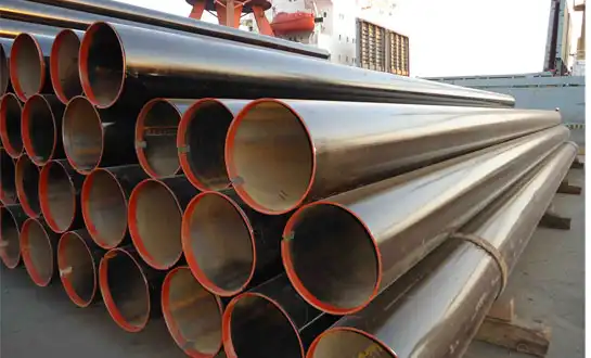
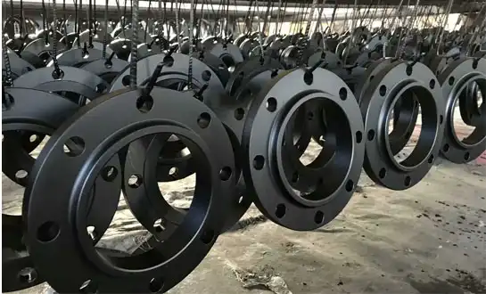
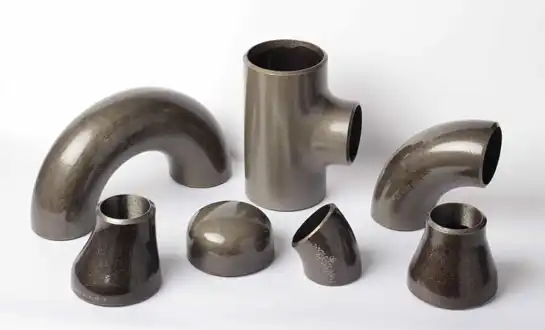
HEBEI RAYOUNG PIPELINE TECHNOLOGY CO., LTD. brings decades of expertise delivering precision-engineered custom pipe bends for demanding industrial applications worldwide. We provide diverse industrial pipe fittings, including buttweld carbon steel elbows, tees, reducers, and flanges ensuring secure connection points throughout your piping infrastructure. Our product lineup includes solutions for all design requirements ranging from standard configurations to custom pipe bends manufactured with exact radius specifications, specialized materials, and precise dimensional tolerances your unique project demands. Backed by GOST-R and SGS certifications and ISO 9001:2015 quality validation, we serve as your dependable carbon steel pipe supplier consistently delivering excellence to domestic and global markets. Our engineering team collaborates closely with clients, providing technical support for radius calculations, material selection, and optimization strategies. Contact our specialists today at info@hb-steel.com to discuss your custom pipe bends requirements and discover how HEBEI RAYOUNG PIPELINE delivers the performance, precision, and long-term durability your infrastructure projects deserve.
References
1. American Society of Mechanical Engineers. (2023). ASME B16.9: Factory-Made Wrought Buttwelding Fittings. New York: ASME Press.
2. Crane Company. (2022). Flow of Fluids Through Valves, Fittings, and Pipe: Technical Paper No. 410. Stamford: Crane Company.
3. Idelchik, I. E. (2021). Handbook of Hydraulic Resistance, Fifth Edition. New York: Begell House Publishers.
4. Nayyar, M. L. (Ed.). (2023). Piping Handbook, Ninth Edition. New York: McGraw-Hill Education.
5. Peng, L. C. & Peng, T. L. (2021). Pipe Stress Engineering: Principles and Applications. New York: ASME Press.
6. Zappe, R. W. (2024). Valve Selection Handbook: Engineering Fundamentals for Selecting the Right Valve Design. Houston: Gulf Professional Publishing.

Need a quote? Want to see samples? Just say hello. We’re friendly. We’re fast. And we’re ready when you are.
Welcome to RAYOUNG – Strong Pipes, Stronger Promise